
How to understand the dielectric loss of capacitors.
Category: Technical Articles
2020-11-13
A. Capacitor media loss.
In an AC circuit, the phase difference between the voltage and current on an ideal capacitor is 90 °, and the relationship is expressed as follows:
Q = CV
for ac bias,
V = V0Sinot
Here V0 is the amplitude of the sinusoidal signal and ω is the frequency.
ThereforeQ = CV0Sinot
And the currentI = dQ/dt = d/dTCV0Sinot
ThereforeI = CV0Cosot
DueCosωt = Sin(ωt 90°)
Therefore, the current phase is 90 ° ahead of the voltage phase. However, the actual medium is not an ideal device, the material resistivity cannot be infinite, and the delay effect or "relaxation time" of the polarization mechanism with frequency will always produce losses.
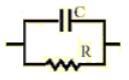
The above model is for an "ideal" capacitor and must be modified in practice; the actual capacitor model can be seen as an ideal capacitor in parallel with an ideal resistor.
At this time, the AC voltage on the capacitor is
V = V0Sinot
The current through the ideal capacitor is
Ic = CV0ωCosωt
For ideal resistors
IR= V/R = V0/R Angles
So the total current is
Ic and = Inet= CV0OCosot V0/R Angles
The addition of the two currents in the above equation indicates that the partial current (I. e., the portion that passes through the resistor) is not 90 ° out of phase with the voltage. The phase difference angle between the actual current and the ideal current is constant, and the tangent value of this angle is defined as the loss tangent or loss factor, as shown in the figure below.
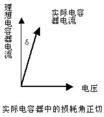
The loss tangent, Tan δ, is an intrinsic property of the material and does not depend on the geometry of the capacitor. The loss tangent has a great influence on the application of dielectric materials in the electronic field. In practice, it is often found that materials with lower dielectric constants have lower dissipation factors. High-K materials with a strong polarization mechanism also have a high loss factor.
B. The frequency effect of media loss.
As mentioned above, the frequency range used by the dielectric material has a significant effect on its polarization mechanism, mainly on the polarization "relaxation" process or time delay of the material with the reversal of the AC electric field. The relaxation time of the instantaneous polarization process is short, and the relaxation time of the delayed polarization process is long. Among the atoms and ions that make up the ceramic medium, the latter causes greater dielectric loss. When the frequency of the external electric field is synchronized with the time period of the relaxation process, the loss value is the largest. In short, when the relaxation time is very different from the period of the external electric field, the loss is very small:
(A) Relaxation time>> electric field frequency, small loss
(B) Relaxation time <
(C) Relaxation time = electric field frequency, maximum loss
Under the condition of (a), the polarization response speed is much smaller than the speed of the external electric field reversal, and the ions can not keep up with the change of the electric field, so there is no heat loss. (B) On the contrary, the polarization process can easily follow the electric field frequency without delay and without loss. However, under the condition of (c), although the ions can keep up with the change of the electric field, they are limited by the relaxation time, so that the maximum loss occurs.
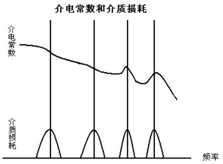
The relaxation time of ceramic media composed of polycrystals is always outside the spectral range. The dielectric loss is consistent with the change in dielectric constant with frequency and is related to the polarization mechanism, as shown in the figure below. In high-frequency applications, a quality factor called "Q factor" is often used, which is equal to the inverse of the loss tangent:
Q = 1/tanδ
Latest information
Address: Eastern New Area, High tech Development Zone, Yiyang City, Hunan Province, China
Foshan Office: Shenye City, Beijiao Town, Shunde District, Foshan City, Guangdong Province,China
Technical support: 86-13617378722 (Mr. Li)
Shenzhen Office: Jinplace Mingxuan, Fuqiang Road, Futian District, Shenzhen,China
Copyright © Hunan Adio Electronic Technology Co., Ltd.