
How to understand the electrostatic capacity of capacitors
Category: Technical Articles
2020-11-13
A. Capacitance
The basic characteristic of a capacitor is the ability to store charge (Q), and the value of Q is proportional to the capacitance (C) and the applied voltage (U).
Q = Cu
The charging current is therefore defined:
= Dq/dt = cdu/dt
When the voltage applied to the capacitor is 1 volt, the charging current is 1 ampere, and the charging time is 1 second, we define the capacitance as 1 farah.
C = Q/U = Coulomb/Volt = Farah
Since the farah is a large unit of measurement, it is difficult to achieve in actual use, so the fraction of the farah is usually used, namely:
Picofa (pF) = 10-12F
Nafa (nF) = 10-9F
Micromethod (mF)= 10-6F
B. Capacitance influencing factors
For any given voltage, the capacitance of a single-layer capacitor is proportional to the geometry and dielectric constant of the device:
= If/f
K = dielectric constant
A = Electrode area
t = thickness of dielectric layer
f = conversion factor
In the imperial unit system, f = 4.452, dimensions a and t are expressed in inches, and capacitance is expressed in picofarads. For example, a single-layer capacitor has an electrode area of 1.0 × 1.0 ", a dielectric layer thickness of 0.56", and a dielectric constant of 2500,
C = 2500(1.0)(1.0)/4.452(0.56)= 10027 PF
If the metric system is used, the conversion factor f = 11.31 and the unit of size is changed to cm,
C = 2500(2.54)(2.54)/11.31(0.1422)= 10028 PF
As discussed above in relation to capacitance and geometry, both increasing the electrode area and decreasing the thickness of the dielectric layer provide greater capacitance. However, it is impractical for a single layer capacitor to endlessly increase the electrode area or decrease the dielectric layer thickness. Therefore, the concept of a parallel array of stacked capacitors was proposed to fabricate a complete device with a larger specific volume capacitance, as shown in the following figure.
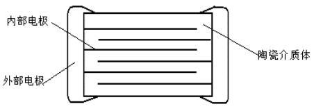
In this "multilayer" structure, the electrode area A is greatly increased due to the parallel arrangement of the multilayer electrodes and the very thin dielectric layer between the opposing electrodes, so that the capacitance C increases as the factor N (number of dielectric layers) increases and as the thickness t′ of the dielectric layer decreases. Here A' refers to the overlapping area of the overlapping electrodes.
0 = X'HQ/4.452(f)
The capacity previously obtained on a monolithic capacitor of 1.0 × 1.0 × 0.56 "can now be obtained if the same dielectric material is used, and a multilayer component with a 30-layer dielectric phase with a thickness of 0.001" and a size of only 0.050 × 0.040 × 0.040 "is added (here the overlapping electrode area A' is 0.030 × 0.020").
C = 2500(0.030)(0.020)30/4.452(0.01)= 10107 PF
The above example shows that the same capacitance can be provided in the case where the size of the multilayer structure capacitor is 700 times smaller than that of the single layer capacitor. Therefore, by optimizing the geometric dimensions, selecting a dielectric material with a very high dielectric constant and good electrical properties (maintaining good insulation resistance and dielectric strength after forming a thin layer structure), a component with a maximum capacitance volume factor can be designed and manufactured.
Latest information
Address: Eastern New Area, High tech Development Zone, Yiyang City, Hunan Province, China
Foshan Office: Shenye City, Beijiao Town, Shunde District, Foshan City, Guangdong Province,China
Technical support: 86-13617378722 (Mr. Li)
Shenzhen Office: Jinplace Mingxuan, Fuqiang Road, Futian District, Shenzhen,China
Copyright © Hunan Adio Electronic Technology Co., Ltd.