
How to understand insulation resistance IR
Category: Technical Articles
2020-11-13
Insulation resistance characterizes the ability of a dielectric material to resist leakage current under a DC bias gradient.
There are no electrons in the atomic structure of the insulator that can move freely under the effect of the strength of the external electric field. For ceramic media, the electrons are firmly bound by ionic and covalent bonds, and the resistivity of the material can be almost defined as infinity in theory. But in fact, the resistivity of the insulator is finite, not infinite, because the impurities and defects in the atomic crystal structure of the material will lead to the appearance of charge carriers.
In oxide ceramics, such as titanates, the presence of charge carriers and the presence of vacant sites (vacancies) and interstitial ions in the crystal structure of the material can be inferred by defect stoichiometry, I .e., anion and cation charge imbalance. For example, an Al3 cation to replace a Ti4 position, producing a net negative charge. Similarly, if the ratio of oxygen ions to other ions is insufficient to maintain the desired valence, a net positive charge will be produced. The latter situation is very likely to occur under low oxygen partial pressure sintering and "reduction" sintering conditions, and severe reduction will reduce the resistivity of the titanate and show semiconductor properties.
The appearance of interstitial ions is due to the random mobility of ions, which is related to temperature; the increase of temperature can make the ions obtain more heat energy to overcome the effect of energy barrier, and the degree of ion diffusion is intensified. Under the action of the applied electric field, the diffusion is no longer random, but along the direction of the electric field potential gradient, resulting in leakage current.
Therefore, the insulation resistance of the chip capacitor depends on the dielectric material formulation, the process (sintering) and the temperature at which it is measured. The insulation resistance of all media will decrease with the increase of temperature, and a very large decrease process can be observed in the temperature characteristic range of MIL from low temperature (-55 ℃) to high temperature (125 ℃).
When measuring the insulation resistance of a capacitor, it is important to consider the relationship between insulation resistance and capacitance. The capacitance value is inversely proportional to the insulation resistance, that is, the higher the capacitance, the lower the insulation resistance. This is because the capacitance and leakage current are proportional to each other, which can be explained by Ohm's law and specific volume capacitance. Ohm's law states the relationship between current (I), voltage (U) and resistance (R) in a conductor:
I = U/R
However, resistance (R) is a physical quantity related to size and also related to the intrinsic resistivity of the material, as shown below:
Watch = ρL/A
where L = conductor length
A = Conductor cross-sectional area
So the current (I) can be expressed:
I = UA/ρL
Considering the leakage current (I) through the insulator in ceramic capacitors can also be expressed by the above relationship:
I = VA'/ρt
Here.
U = Test voltage
A' = effective electrode area
ρ = dielectric resistivity
t = thickness of dielectric layer
As can be seen from the above relationship, for a given test voltage, the leakage current is proportional to the effective electrode area of the capacitor and inversely proportional to the thickness (and resistivity) of the dielectric layer, I .e:
I ∝ A’/t
Similarly, the capacitance (C) is proportional to the effective electrode area and inversely proportional to the thickness of the dielectric layer, I .e:
US = BattAlibabaon/4.452
Here K = dielectric constant
A' = effective electrode area
t = thickness of dielectric layer
Therefore
C ∝ A'/t and I ∝ C
The leakage current (I) is inversely proportional to the insulation resistance, I .e:
IR ∝ 1/C
Based on the above relationship, the following points can be summarized:
(a) The insulation resistance is a function of the test voltage, and the leakage current is proportional to the applied voltage:
I = UA’/ρt 或 IR =ρt/UA’
(B) For any given capacitor, the insulation resistance depends largely on the intrinsic resistivity (ρ) of the dielectric material, as well as on the material formulation and the temperature at which it is measured.
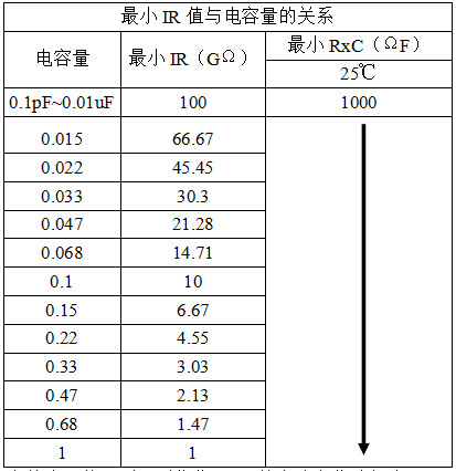
(c) The measured value of capacitor insulation resistance (IR) is inversely proportional to capacitance, that is, IR is a function of capacitance. Therefore, the minimum standard of product IR in industrial applications is determined by resistance (R) and capacity (C),(R×C), as shown in the following table. The EIA standard requires that R×C exceed 1000 ohm-farad (usually expressed as 1000 megohm-microfarad) at 25 ℃ and 100 ohm-farad (only 10% of the value in the following table) at 125 ℃.
Usually, the dielectric has a very high resistance value, which is often expressed in 10 times the high power of ohms when measured:
1 teraohm (TΩ)= 1012Ohm
1 GΩ = 109Ohm
1 megohm (MΩ)= 106Ohm
In addition to material and size, there are other physical factors that affect the insulation resistance of a capacitor.
(A) Surface resistivity: Because the surface absorbs impurities and moisture, the surface resistivity of the medium is inconsistent with the bulk resistivity.
(B) Defects: The medium is composed of a polycrystalline ceramic polymer, and the grain boundaries and pores in its microstructure always reduce the intrinsic resistivity of the material. From a statistical point of view, the probability of these physical defects is proportional to the volume of the component and the complexity of the structure. Therefore, for an element with a larger size, a larger electrode area and a larger number of electrode layers, the resistivity and dielectric strength are lower than those of a small-sized element.
Latest information
Address: Eastern New Area, High tech Development Zone, Yiyang City, Hunan Province, China
Foshan Office: Shenye City, Beijiao Town, Shunde District, Foshan City, Guangdong Province,China
Technical support: 86-13617378722 (Mr. Li)
Shenzhen Office: Jinplace Mingxuan, Fuqiang Road, Futian District, Shenzhen,China
Copyright © Hunan Adio Electronic Technology Co., Ltd.