
How to understand Q and ESR
Category: Technical Articles
2020-11-13
An important performance index for evaluating high-frequency chip capacitors is the quality factor Q, or the equivalent series resistance (ESR) associated with it. In addition to providing high-performance RF components, the company is also committed to providing customers with accurate and complete performance data. To achieve this goal, in this article we discuss in detail the measurement and understanding of Q and ESR.
In theory, a "perfect" capacitor should behave as a non-impedance element with an ESR of zero ohms and pure capacitive resistance. Regardless of the frequency, the current through the capacitor will be exactly 90 degrees ahead of the voltage phase.
In fact, the capacitance is not perfect, there will be more or less a certain value of ESR. The ESR of a particular capacitor varies with frequency and is related by an equation. This is because the source of ESR is the characteristics of the conductive electrode structure and the structural characteristics of the insulating medium. For modeling analysis, ESR is treated as a single series parasitic element. In the past, all capacitance parameters were measured at the standard frequency of 1MHz, but today is a higher frequency world, 1MHz conditions are far from enough. The typical parameter values given by a high-frequency capacitor with excellent performance should be: 200MHz, ESR = 0.04 Ω;900MHz, ESR = 0.10 Ω; 2000MHz, ESR = 0.13 Ω.
The Q value is a dimensionless number numerically equal to the reactance of the capacitor divided by the parasitic resistance (ESR). The Q value varies greatly with frequency because both reactance and resistance vary with frequency. The change of frequency or capacity will make the reactance change greatly, so the Q value will also change greatly. It can be reflected in formulas I and II:
Formula 1: | Z | = 1 / ( 2πf C)
Where | Z | is the absolute value of reactance, unit Ω; F is frequency, unit Hz;C is capacity, unit f.
Equation 2: Q = | Z | / ESR
where Q represents the "quality factor", dimensionless; | Z | is the absolute value of the reactance, in Ω; and ESR is the equivalent series resistance, in Ω.
It is not credible to use the S-parameters collected from the vector network analyzer to derive the ESR. The main reason is that the accuracy of this data is limited by the accuracy of the network analyzer in a 50 Ω system (typical ± 0.05 dB measurement accuracy is insufficient in the low loss region of capacitance as low as ± 0.01 dB). Similarly, the use of LCR meters to measure the Q and ESR of high-Q devices is also implausible. This is due to the fact that when the Q value of the element is very high, the LCR meter cannot correctly distinguish between a very small resistance (R) and a very large reactance (Z). Therefore, the measurement method of ESR and Q of high-Q capacitors is generally used as the industry standard resonant line test method.
This test method has long been an industry standard for measuring Q and ESR at radio frequencies RF. Because the method relies on the frequency accuracy of the signal generator (which can be measured very accurately), the data is sampled in a very precise manner. Modern capacitance ESR is so small that the accuracy of this measurement method is only close to ± 10%. However, this is still the most accurate and effective method of measuring Q and ESR at radio frequency RF.
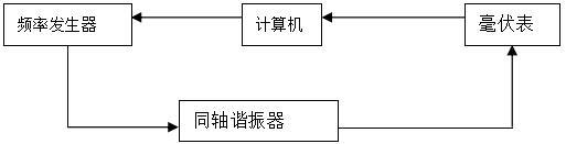
Test method:
Latest information
Address: Eastern New Area, High tech Development Zone, Yiyang City, Hunan Province, China
Foshan Office: Shenye City, Beijiao Town, Shunde District, Foshan City, Guangdong Province,China
Technical support: 86-13617378722 (Mr. Li)
Shenzhen Office: Jinplace Mingxuan, Fuqiang Road, Futian District, Shenzhen,China
Copyright © Hunan Adio Electronic Technology Co., Ltd.